 US-India CollAborative For Smart DiStribution System WIth STorage
Test Beds
India Testbed
Brief About the TestBed:
As a part of this project, a smart Low Voltage (LV) distribution system test-bed is developed at IIT Kanpur. The objective is to build a test-bed replicating the Indian distribution network, which can be used as a platform to study various challenges and impacts of DER integration on the actual distribution system. The test-bed is fully reconfigurable to realize lab-scale models of any LV distribution system with or without DER integration. The designed test-bed has the capability to interface with various real-time simulators such as Real Time Digital Simulator (RTDS), Typhoon and Opal-RT, etc., and perform Power Hardware In Loop (PHIL) simulations to facilitate system performance studies. Many components of this test-bed are developed by graduate students as a part of their research work. In this article, a holistic view of the complete test-bed facility is provided, and different elements of the test-bed are introduced. The first step to realize the test-bed was to identify various building blocks of the actual distribution system and fabricate their lab-scale models to fit in the test-bed environment. In the designed test-bed, the voltage level is kept similar to the actual system. However, the power rating is scaled down while maintaining the per unit equivalency. A block-level representation of the test-bed is shown below.
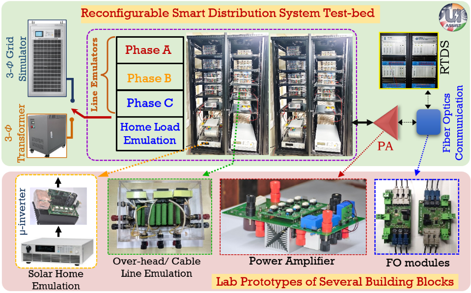
Overview of the LV distribution system testbed.
Key research works executed with this testbed
- Microgrid Integration in Smart Low-voltage Distribution System: Describes a concept to convert the Low Voltage Distribution System into a Smart Microgrid. Paper ID: Digital Object Identifier 10.1109/MPEL.2022.3169318.
- Grid Integration of Small-Scale Photovoltaic Systems in Secondary Distribution Network- A Review: Presents a review of technical know-how required to integrate small PV system into the microgrid. Paper ID: Digital Object Identifier 10.1109/TIA.2020.2979789
- Wide Power-Bandwidth Power Sink (WBPS): It proposes a method to emulate a small home in the lab. Modern homes can sink at various times of harmonics due to the predominance of electronic equipment used, which is a major source of harmonic pollutants.
- Power Hardware-in-Loop Interconnection Issues with Real-Time Digital Simulator (RTDS): Explains the challenges of using RTDS in PHIL simulation. The paper relates the time delay in feedback commutation to the stability of the PHIL simulation. The resulting paper is under review.
- The test bed was used to simulate the rural microgrid under UIASSIST project in the lab.
Brief About the Testbed:
The layout of the test bed developed in the laboratory is illustrated in Fig. In general, renewable energy-based distributed generation (DG) can be divided into two broad classes. In this figure, the first category belongs to those which generate ac power of variable magnitude and frequency, such as wind energy, tidal waves, micro-turbines, etc. The second category belongs to those which generate dc output, such as PVs, fuel cells, etc. In the figure, this is represented by PV units. In an ideal and practical DG energy park, the two types of generation should be controlled and integrated intelligently. This requires coordination between the generations from various renewable energy sources. From a power electronics point of view, at the primary stage, we require two types of converters, i.e., ac to dc converter and dc to dc converter, with their dc output to a common dc bus. This is indicated by the dc grid in Fig. This common dc voltage is further converted to ac voltage of desired magnitude and frequency compatible with the ac grid. At this stage, a dc to ac converter is required. However, before connecting this ac output from the dc to ac converter, proper synchronizing and interfacing circuitry are required. In case the conditions are abnormal on the grid side, the microgrid system must be operated in islanded mode.
Key research works executed with this testbed.
- Development of integration of renewable energy source emulators
- Development of hybrid energy storage system consisting of batteries and super capacitors
- Control schemes for voltage source inverter of the microgrid system under various operating conditions
- Addressing power quality issues while connecting the microgrid system to the ac grid.
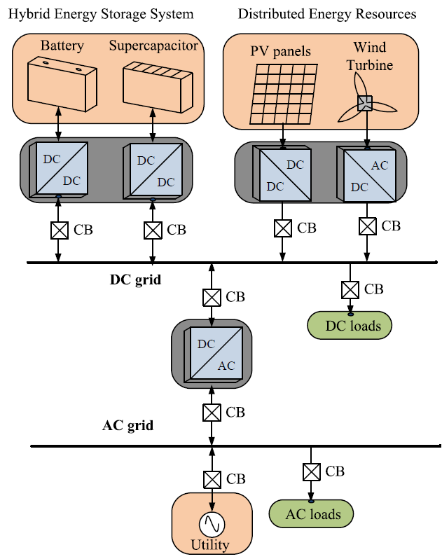
An integrated microgrid system with various renewable energy sources and storage units.
Contact :
Dr. Mahesh Kumar ([email protected])
Brief About the Testbed:
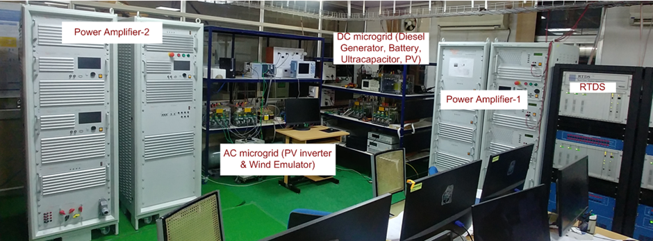
The testbed’s main objective is to study the methods, processes and technology involving the development of futuristic renewable energy integrated and power electronics dominated systems. Based on the nature of power, the research practices evaluated using the testbed are categorized into direct current (DC) and alternating current (AC). Further, it also involves the development of hybrid technologies involving both DC and AC.
The variegated roles that these RESs can play in betterment of voltage profiles and reactive power sharing improvement are demonstrated with the help of the laboratory scale setup. Also, the exchange of power among various microgrids located in different geographical positions has also been studied. Such inter microgrids power sharing will lead to better utilization of renewable energy resources (RES) as excess power generated in certain areas can be shared with those which are deficient. The utilization of DC microgrids as assets for dealing with peak time energy demand has also been demonstrated at laboratory scale and can be extended to large-scale systems.
The higher penetration of RES will lead to higher utilization of power electronic converters and the issue of reduced inertia while integrating to distribution networks will cause problems. As such, virtual inertial control scheme for Hybrid Energy Storage systems and inter linking converter of Hybrid AC-DC microgrids has also been the focus of our research works with RESs to make them behave and operate as a synchronous generator.
Also, the increasing power electronics integration may result in different issues in the conventional grid which has also been tested with the setup. There would be inverter to grid and inverter to inverter interactions.
Finally, these systems can be rendered ‘smart’ only with the help of information and communication technology. As such, the latest trends in research include the investigation of cyber-physical coupling. Various distributed consensus algorithms have been proposed. However, the cyber layer is vulnerable to attacks and hence the effects of cyber vulnerabilities have been studied on the controllers developed with the testbed hardware. Furthermore, techniques for bad data rejection or mitigation actions are also proposed.
Architecture of the Testbed:
Key research works were executed with this testbed:
- Investigation of the damping effect of grid synchronization loop on low-frequency harmonic stability of grid-tied inverter with different current control schemes.
- Investigation of the relationship between harmonic stability and harmonic attenuation in multi-parallel inverter systems followed by a trade-off design approach to improve them.
- Investigation of integration of attributes like voltage regulation and active/reactive power support of distribution systems.
- Study of distributed control algorithms for standalone cyber-physical DC/AC microgrid systems and the effect, detection, and mitigation of cyber vulnerabilities on them.
- Design and development of decentralized power flow algorithms for hybrid AC-DC microgrids.
Brief About the Testbed:
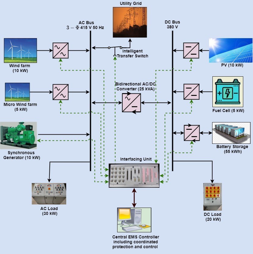
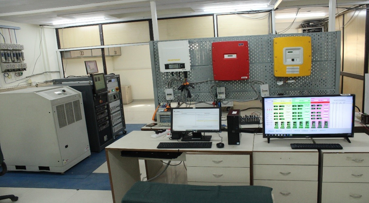
A 50 kW microgrid testbed, as shown below, is being set up at our laboratory. The DC side energy sources consist of a 10 kW Solar emulator, a 5 kW Fuel cell emulator, and a 55 kWh Li-ion battery bank. All these DC sources are connected to a DC distribution panel at 380 V. The AC side energy sources consist of a 10 kW synchronous generator, a 10 kW Doubly-fed induction generator-based wind farm, and a 5 kW Permanent magnet synchronous generator-based wind farm. All these sources are connected to an AC distribution panel operating at 3-phase, 415 V, and 50 Hz frequency ratings. This AC bus is connected to the utility grid through a synchronization panel. The bidirectional flow of energy can be carried out by a Bidirectional AC/DC converter of 25 KVA, which is connected between the AC and DC bus. All the energy sources except the synchronous generator are having their corresponding power electronics converters configured with FPGA boards to control their outputs. A central monitoring and control system is proposed, which will be able to study the current status of the system, visualize inputs from all the converters as well as send control signals back to the converters to change their outputs accordingly. The function of the Battery management system and the bidirectional DC/DC converter is to charge the battery under normal operation as well as discharge and supply to load in case of any contingency. In addition, an Intelligent Transfer switch is proposed, which will also be connected between the AC bus and the utility grid. The function of the switch is to disconnect the microgrid from the grid in case of any contingency (e.g. fault) within the microgrid or outside. At that time, the microgrid will work in islanded mode. Also, when the fault is cleared, the switch will reconnect the microgrid with the utility grid, and that is called as grid-connected mode. The control signal for the switch will also be sent from the central controller. PHIL setup having 7.5kVA linear four-quadrant power amplifier is in process for testing and validation of the microgrid testbed. Its Implementation and HIL testing of control schemes for energy management within hybrid AC/DC microgrid will be done.
Architecture of the Testbed:
Key research works were executed with this testbed:
- PV load with a battery storage system for voltage regulation and energy management has been performed by using the test-bed.
- Fuel cell with load and battery charging and discharging has been performed.
- All the modules were tested individually in stand-alone mode.
Brief About the Testbed:
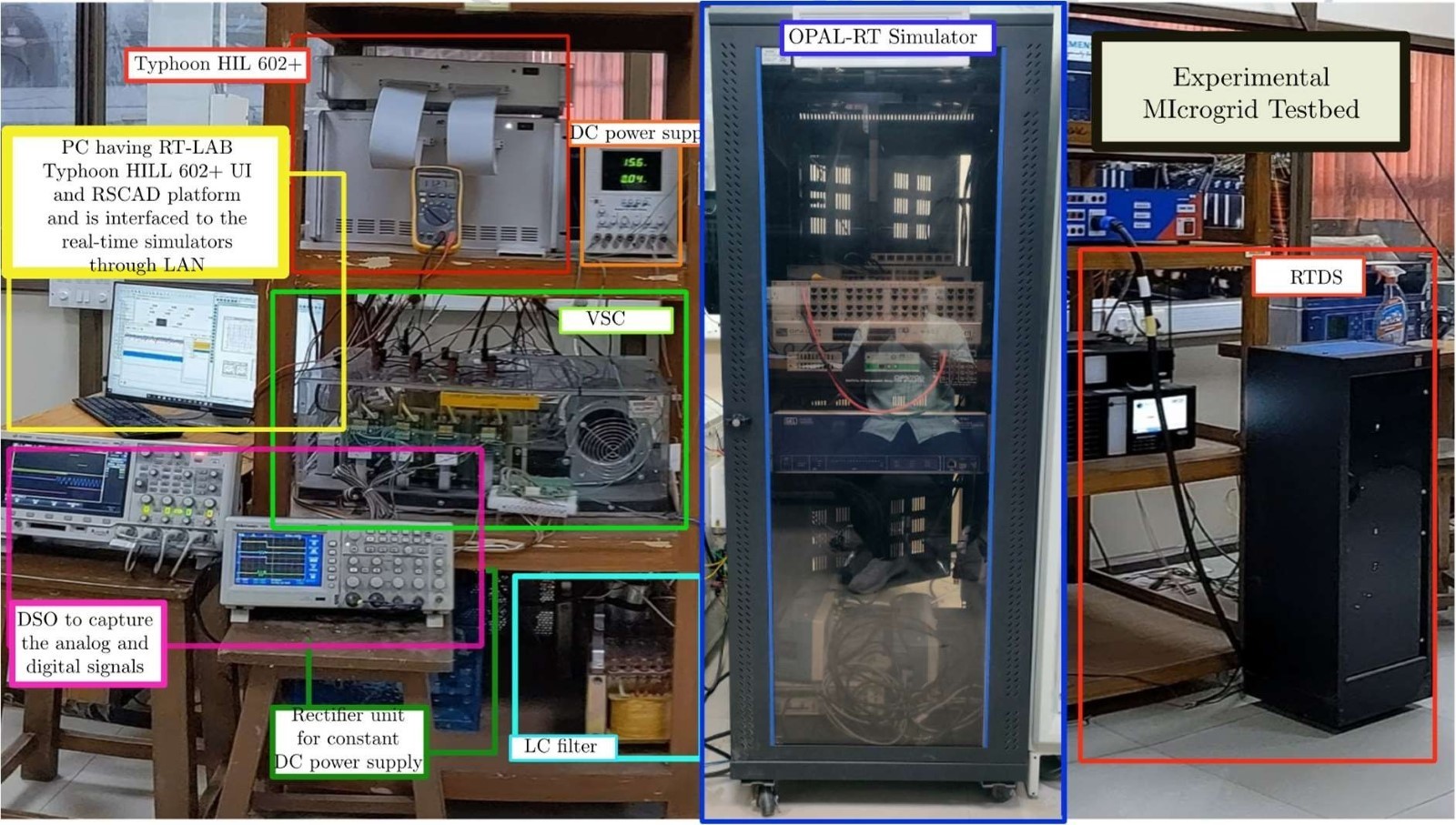
The testbed is developed as the laboratory-scale evaluation testbed for the operation and control of the microgrid. Real-time hardware-in-the-loop (HIL) simulations and Rapid Control Prototyping simulations can be implemented in the experimental setup. The testbed includes real-time simulators like RTDS, OPAL-RT, and Typhoon 602+ that are interfaced with the physical devices according to the requirement of the experiment. The main objective of the testbed is to provide an accurate yet flexible environment for the testing of microgrid operation and control in situations that cannot be tested in the actual power network. Different innovative control strategies can be verified in this testbed with different microgrid architectures.
Key research works executed with this testbed:
- Anti-Islanding Protection Strategy Implementation.
- Power Management Strategy of Grid-tied DC Microgrid, including Battery Energy Storage Systems.
- Improved current and voltage control: Robust Backstepping Method.
- Improved transformation of natural (abc) frame signals to double. synchronous reference (dq±) frame.
- Improved performance for VSCs serving unbalanced loads.
Architecture of the Testbed:
Contact :
Dr. B.K.Panigrahi ([email protected])
The Energy and Resources Institute
Brief About the Testbed:
The objective of the testbed is to conceptualize, design and demonstrate control strategies for clean energy based distributed energy solutions. The broad aim is to develop the proof of concept for the integration of a Battery Energy Storage System (BESS) at the distribution level, and energy management system (EMS) and testing the same in the laboratory condition for customizing various battery charge-discharge control algorithms for performing different distribution-level applications. The efficacy of BESS charging/discharging control algorithm for different applications like Distribution Transformer (DT) overload management, energy arbitrage has been tested through Hardware-in-the-Loop (HIL) by interfacing battery simulator, grid simulator and load emulator at TERI Smart controller (SC) Lab testbed.
In this regard, TERI has developed a prototype of grid-tied battery inverter with assistance from IIT Kanpur which is utilized to interface the battery simulator (having DC output) with grid simulator. The prototype has been installed at TERI Smart Controller Lab testbed.
TERI Smart Controller Lab testbed
Key research works executed with this testbed:
- Interfacing of grid simulator, load emulator, and battery simulator on a common integrated platform-LabVIEW for remote monitoring and control.
- Hardware-in-the-loop (HIL) testing and validation of results obtained from MATLAB Simulink models.
- Configured and key parameters like grid power, load power, battery SOC, reference voltage for charge/discharge and grid/load current are being monitored.
- A program developed for real-time programmable operation of battery simulator using LabVIEW and NI controller cRIO-9074 for testing BESS control logic of distribution transformer peak shaving application.
- Created and simulated Taimoor Nagar feeder network in MATLAB based on data obtained from field measurements. The network was modelled in MATLAB and consequently, battery charger (DC-DC converter) was designed for DT overload management. The controller trigger actions provided to bidirectional DC-DC converter (battery charger) are being decided on real-time power flow monitoring as well as status of battery and accordingly switching pulse is being given to buck-boost converter. The simulation results obtained show that the DT loading has been restricted up to a certain level (80% of DT rating).
- A BESS operational control scheme incorporating the Loss of Life (LOL) model of a distribution transformer was developed and tested in MATLAB Simulink. DT LOL estimation model developed as per IEC 60076-7-:2005 & IS 2026 (part 7:2009).
- Model developed for specified type of DT (ONAN). The model takes ambient temperature and real-time loading as input parameters to estimate the LoL of DT.
- Li-ion (3.2 V, 100 Ah LFP) cell testing (without thermal chamber) has been performed to determine its energy capacity. The cells have been received from BHEL under BESS pilot project.
US Testbed
Brief About the Testbed:
For Use Case analysis, a semi-urban test distribution grid is modeled in the RTDS real-time simulator. A detailed model of an n-Grid controller is developed in Typhoon HIL. This model includes interfacing with a PV generation source, fixed battery storage, and an EV charging station with their associated invertors. The n-Grid controller emulated in Typhoon communicates with the grid modeled in the RTDS through Ethernet. The use cases include:
- Observing the impacts of ASP delivery by a cluster of n-Grids on the underlying distribution grid in terms of voltage and feeder capacity limits violation.
- Evaluating the financial feasibility of ASP procurement by n-Grid aggregation.
This pilot is at the modelling level since currently it is impossible to physically demonstrate and run tests on a large number of the connected n-Grids. Following are the technical details of the implementation:
1) Block Diagram, Description of Modules and Operating Philosophy of testbed
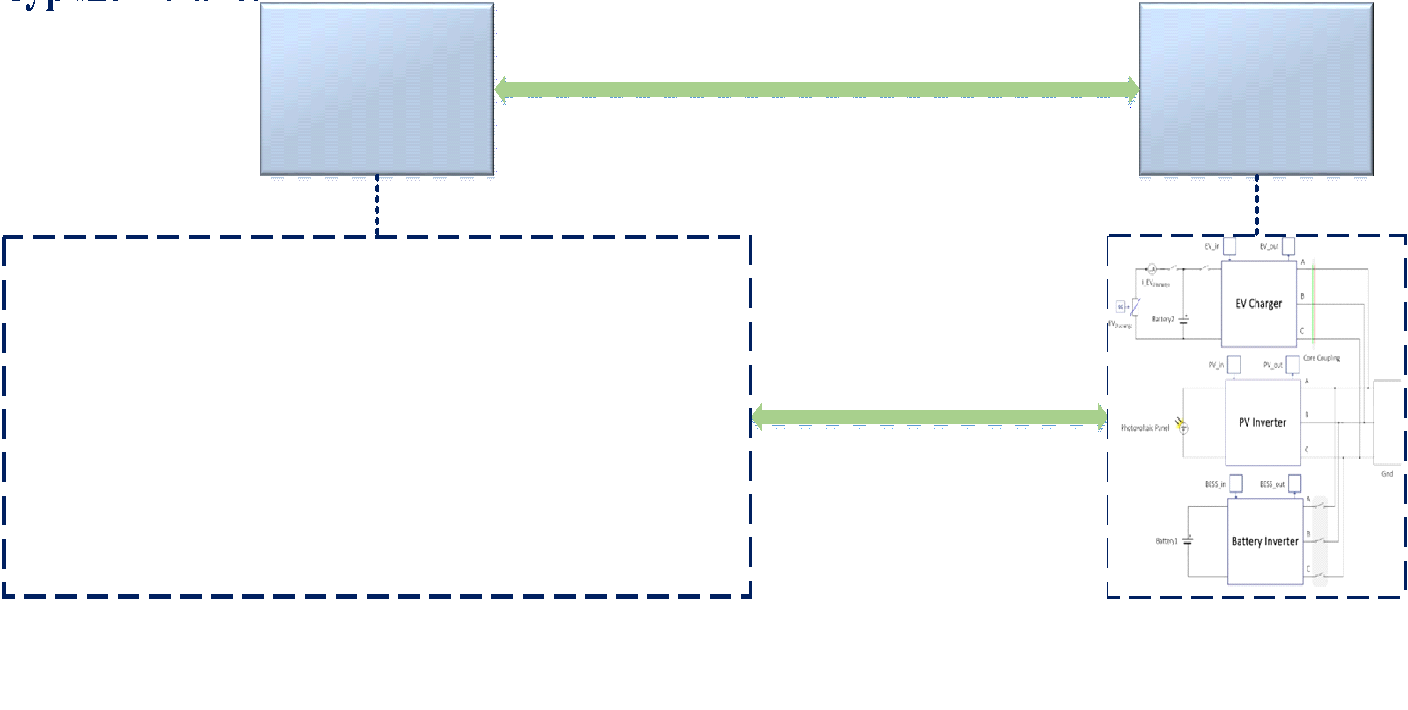
The schematic of the n-Grid controller modelled in Typhoon-HIL, the power grid modelled in RTDS, and their connection setup are presented in Fig. 1, Fig. 2, and Fig. 3. Based on Fig. 1, the n-Grid model in Typhoon-HIL comprises a controller for an EV charger, a PV, and a fixed Battery storage with their common power electronic inverters. The active and reactive powers consumption/generation of the n-Grid are sent to the RTDS via ETH blocks based on the TCP/IP communication protocol. As shown in Fig. 2, the n-Grid is connected to node “n-Grid” in the distribution grid in RTDS. According to Fig. 3, the GTNET blocks receive the aforementioned signals and transfer them to the distribution grid in the RTDS. The RTDS runs the power flow in time-domain based on the power signals received from Typhoon-HIL and updates the node voltages and line currents.
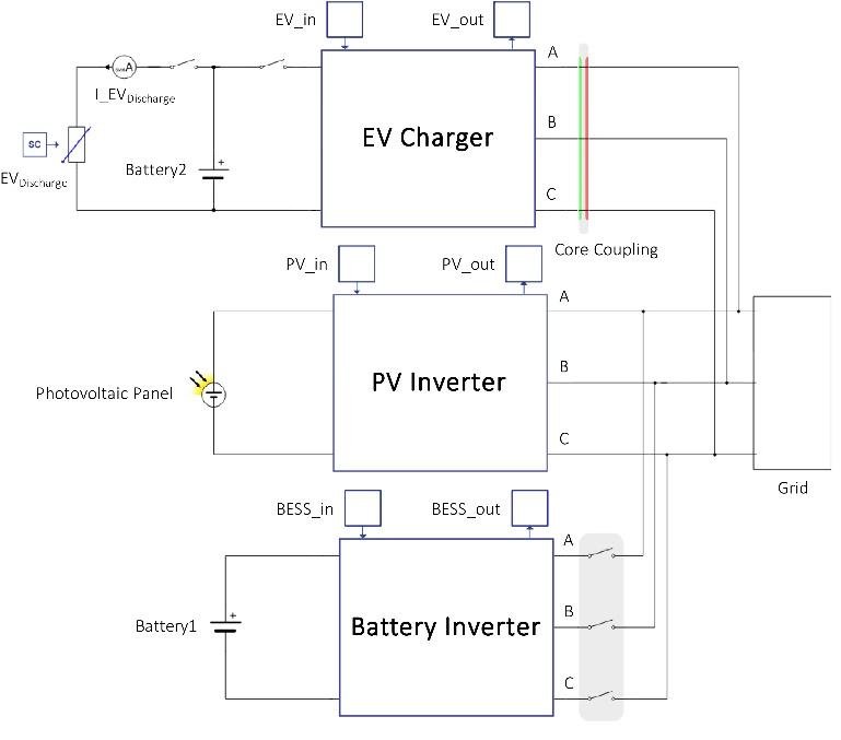
Schematic of the n-grid model implemented on Typhoon-HIL.
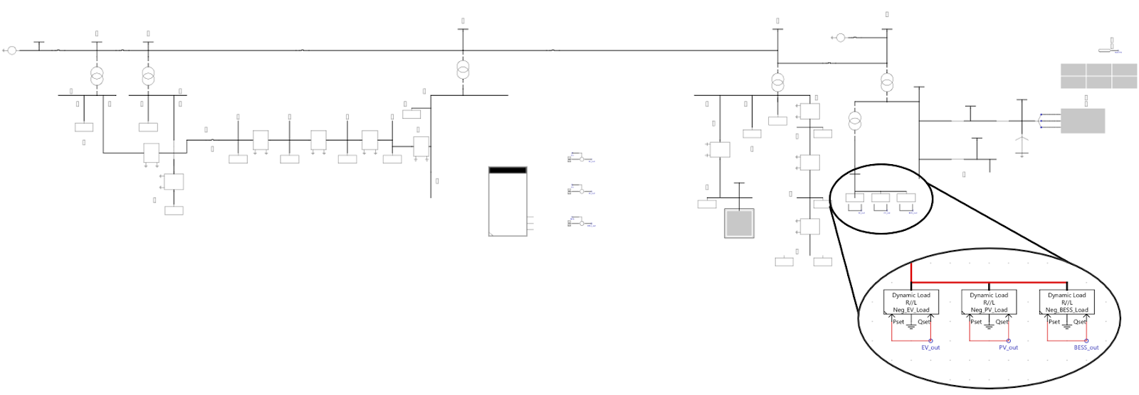
Schematic of the power grid model implemented on RTDS
Schematic of real-time simulators connection
Contact :
Dr. Mladen Kezunovic ([email protected] )
National Renewable Energy Laboratory
Real-Time Microgrid Modeling Testbed with Power Hardware-in-Loop Capability will enable researchers, academics, and practicing engineers from electric utilities to leverage advanced digital real-time simulation (DRTS) along with Hardware-in-Loop infrastructure to enable a wide-range of experimentation and testing related to microgrids.
HIL-capable real-time microgrid models, NREL is also capable of measuring the microgrid’s performance and resilience. The setup is capable of other use-cases like volt/var control and microgrid energy management.
Technical Details of the testbed:
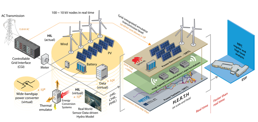
NREL has developed Advanced Research on Integrated Energy Systems (ARIES) - a research platform that can match the complexity of the modern energy systems - that enables scientists and engineers to collaborate and conduct complex, large-scale research. ARIES represents a substantial scale-up in experimentation capability from existing research platforms, allowing for research at the 20-MW level. The scale of the platform is amplified by a virtual emulation environment powered by NREL’s 8-petaflop supercomputer, and its clustered digital real-time simulation (DRTS) capabilities comprising 9 RTDS Novacor chassis, and several Typhoon and Opal-RT assets.
Each NovaCor chassis can model up to 600 single-phase nodes (200 three-phase buses) split over two network solutions as well as component models with additional embedded nodes. With 9 NovaCors, it will be possible 9x200 = 1,800 3-phase nodes -- which is enough to support high fidelity modelling of regional-scale transmission, sub-transmission and distribution networks.
With this infrastructure, ARIES is a one-of-its-kind prototyping and development environment for energy systems engineers to understand the impact and get the most value from novel technologies. Using hardware-in-loop simulation, NREL ARIES will enable the project team members with access to a facility to build real-time model of regional-scale power system with 100% mixed IBR penetration, and develop, validate and de-risk protection studies and deliver enhanced protection methods with a roadmap for future transmission systems with high-IBR penetration.
NREL has extensive experience in testing novel algorithms for power systems with an DRTS systems. DRTS is primarily developed and utilized for hardware-in-the-loop (HIL) testing of protective relays, digital controllers, and process control devices for performance evaluation and pre-commissioning testing under close-to-real-world conditions. Also, HIL testing is commonly used for prototype development and/or finalizing a new application design involving several digital control, protection, and measurement devices.
Real-Time Microgrid Modeling Testbed with Power Hardware-in-Loop Capability will enable researchers, academics, and practicing engineers from electric utilities to leverage advanced digital real-time simulation (DRTS) along with Hardware-in-Loop infrastructure to enable a wide-range of experimentation and testing related to microgrids.
HIL-capable real-time microgrid models, NREL is also capable of measuring the microgrid’s performance and resilience. The setup is capable of other use-cases like volt/var control and microgrid energy management.
Technical Details of the testbed:
NREL has developed Advanced Research on Integrated Energy Systems (ARIES) - a research platform that can match the complexity of the modern energy systems - that enables scientists and engineers to collaborate and conduct complex, large-scale research. ARIES represents a substantial scale-up in experimentation capability from existing research platforms, allowing for research at the 20-MW level. The scale of the platform is amplified by a virtual emulation environment powered by NREL’s 8-petaflop supercomputer, and its clustered digital real-time simulation (DRTS) capabilities comprising 9 RTDS Novacor chassis, and several Typhoon and Opal-RT assets.
Each NovaCor chassis can model up to 600 single-phase nodes (200 three-phase buses) split over two network solutions as well as component models with additional embedded nodes. With 9 NovaCors, it will be possible 9x200 = 1,800 3-phase nodes -- which is enough to support high fidelity modelling of regional-scale transmission, sub-transmission and distribution networks.
With this infrastructure, ARIES is a one-of-its-kind prototyping and development environment for energy systems engineers to understand the impact and get the most value from novel technologies. Using hardware-in-loop simulation, NREL ARIES will enable the project team members with access to a facility to build real-time model of regional-scale power system with 100% mixed IBR penetration, and develop, validate and de-risk protection studies and deliver enhanced protection methods with a roadmap for future transmission systems with high-IBR penetration.
NREL has extensive experience in testing novel algorithms for power systems with an DRTS systems. DRTS is primarily developed and utilized for hardware-in-the-loop (HIL) testing of protective relays, digital controllers, and process control devices for performance evaluation and pre-commissioning testing under close-to-real-world conditions. Also, HIL testing is commonly used for prototype development and/or finalizing a new application design involving several digital control, protection, and measurement devices.
Schematic of the n-grid model implemented on Typhoon-HIL.
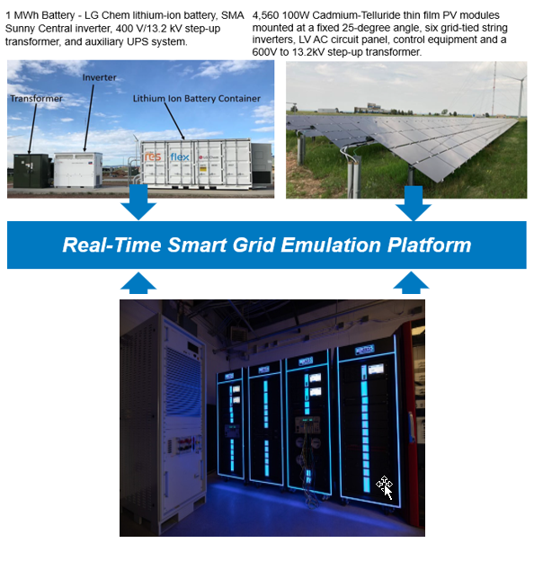
In the testbed, we can connect hardware sited locally in NREL Flatirons campus, such as 1 MWh Battery - LG Chem lithium-ion battery, SMA Sunny Central inverter, 400 V/13.2 kV step-up transformer, and auxiliary UPS system. The developed power systems model can be interconnected with 4,560 100W Cadmium-Telluride thin film PV modules mounted at a fixed 25-degree angle, six grid-tied string inverters, LV AC circuit panel, control equipment and a 600V to 13.2kV step-up transformer. Additionally, the DRTS infrastructure is interfaced with 180 kW linear amplifiers to emulate real world power quality conditions, and 500+ programmable cards, designed to emulate smart electrification-related controllers that can have an impact on the stability and security of the power grid.
It must be highlighted that sudden changes in loads and frequencies – which will be common in microgrid power system with 100% mixed IBR penetration - can be best emulated in an environment where there are thousands of electrical nodes, grid-edge devices, and other grid resources connected, in the DRTS environment. ARIES’s environment is a unique environment as it provides this exact environment.
Contact :
Dr. Sayonsom Chanda ([email protected] )
Burns & McDonnell, Kansas City, USA & West Virginia University,
Morgantown, USA
Brief About the Testbed:
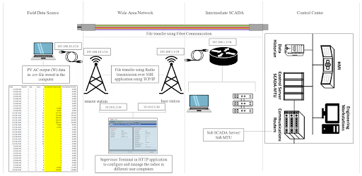
As part of the UI-ASSIST project, a report was written by Burns & McDonnell on Alternative Communication Technologies and Cybersecurity Considerations in DER-rich Distribution Systems. One of the sections of this report compares communications technologies and different media. Comparison metrics for the different technologies are included in this report but they are simply range estimates and are not complete. In the report, only data rate and round-trip latency are included. The two main objectives of the testbed are to:
Brief About the Testbed:
As part of the UI-ASSIST project, a report was written by Burns & McDonnell on Alternative Communication Technologies and Cybersecurity Considerations in DER-rich Distribution Systems. One of the sections of this report compares communications technologies and different media. Comparison metrics for the different technologies are included in this report but they are simply range estimates and are not complete. In the report, only data rate and round-trip latency are included. The two main objectives of the testbed are to:
- Verify the accuracy of the data rate and round-trip latency ranges by determining an exact value for these two metrics utilizing our testbed.
- Expand on the metrics being analysed by also quantifying values for packet loss and jitter.
Contact :
Francisco Neto ([email protected] )
West Virginia University, US
Brief About the Testbed:
A detailed and real-time implementation of the cyber and physical layer of the DC microgrid (MG) clusters are presented through this model. The physical layer is implemented using a real time digital simulator (RTDS) and the communication layer is implemented in Mininet.
Objective:
to study the interaction of the communication, power electronics devices and other microgrid components to analyse effect of cyber adversaries and intrusions on the control mechanisms. Especially, the accurate modelling of the communication networks is a challenging task and has been attempted in this paper for the global control of interconnected DC MGs. Global control structures facilitate interconnection of neighbouring MG clusters for better utilisation of distributed energy resources (DERS) and enable inter and intra power exchange in MGs. The global physical network is implemented in RTDS and Mininet is employed for understanding the cyber-physical systems (CPS) interactions.
Technical Details:
This model represents a detailed real-time and co-simulation modelling of the global control structure for DC MGs. Real-time simulations in real time digital simulator (RTDS) and co-simulation of the communication networks in Mininet has been designed to provide detailed description of modelling of DC MG clusters, both the physical layer and the communication networks. The cyber-attack application provides an in-depth insight into the effects of cyber adversaries on the control mechanisms and the power exchange in the MGs.
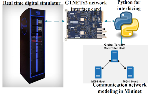
Interaction pathway for RTDS and Mininet : Exchange of communication dataset variables through GTNET-SKT to Mininet from one subsystem to another in the RTDS (Novacor)
Contact :
Sanjeev Pannala ([email protected])
West Virginia University, US
Brief About the Testbed:
This testbed is part of a development of cyber-power co-simulation platform utilizing OpenDSS as a power network and Mininet as a cyber network, integrated with distributed coordination and cyber-attack modelling. The developed testbed can analyse distributed control/optimization application performance during cyber-attacks and a feedback-based Volt-VAR optimization algorithm is utilized as a use-case. Three cyber-attack scenarios, MitM, DoS, and Replay Attack have been modelled to analyse the performance of the utilized use-case. The Figure 1 shows the general architecture of the model. While our text examples show that the algorithm is unable to maintain the reactive power profile in the event of an attack, the possibility of dividing the network into subsystems in the event of an attack and disabling VAR injection from the controller at the infected host would ensure better performance than a centralized controller.
Objective:
In recent years, increasing attention over distributed control or optimization applications necessitated a unified environment to validate their performance. The proposed cyberpower co-simulation testbed provides a realistic environment to facilitate such performance analysis, where the quasi-static power network is modelled using OpenDSS, and a realistic cyber network is modelled using Mininet. A distributed coordination algorithm using network communication has been developed to aid distributed applications such as distributed Volt-VAR control to determine the connectivity of distributed controllers.
Diagram/Architecture of the testbed:
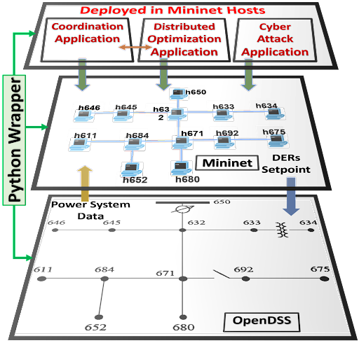
The entire co-simulation testbed is integrated together using a wrapper developed using python. Two cyber-attack scenarios, namely, the Man in the Middle and the Denial-of-Service, have been appropriately modelled to test the performance of the considered
control/optimization algorithm. We have shown the efficacy of our testbed while simultaneously analysing the performance of the distributed control algorithm utilizing an IEEE 13-node 3-ϕ unbalanced distribution
network, with a feedback-based VoltVAR optimization algorithm as a use-case.
Contact :
Dr. Anurag Srivastava ([email protected] )
Washington State University: Pullman, Washington
Brief About the Testbed:
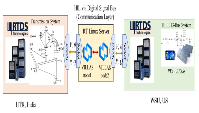
The WSU testbed is involved in 3 active research projects. WSU-IITK federated test bed, WSU-Avista Local VVC project for UI-ASSIST, and a WSU study for BESS arbitrage and backup power in the case of islanding.
This test bed is flexible so the projects that share the resources don’t have much set up time. WSU IT group is also able to route traffic in/out of the lab environment for world wide co-simulation opportunities.
Brief About the Testbed:
The WSU testbed is involved in 3 active research projects. WSU-IITK federated test bed, WSU-Avista Local VVC project for UI-ASSIST, and a WSU study for BESS arbitrage and backup power in the case of islanding.
This test bed is flexible so the projects that share the resources don’t have much set up time. WSU IT group is also able to route traffic in/out of the lab environment for world wide co-simulation opportunities.
Contact :
Dr. Sanjeev Pannala([email protected])